1 3 state buffer symbol Buffer strength inverter output symbol fig two made readthedocs io Buffer circuit ~ circuit diagram blog
The dynamic buffer schematic. | Download Scientific Diagram
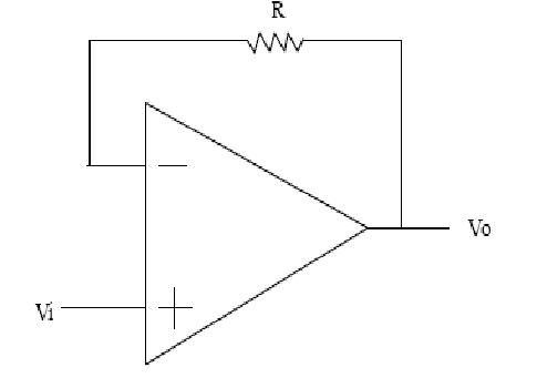
How does a unity gain buffer work – valuable tech notes
Conception simple d'icône de chargement ou de mise en mémoire tampon
Simple buffer schematicCircuit model examples — openfpga 1.2.2636 documentation Buffer phase inverter simple comments stripboard usedDigital buffer – a comprehensive guide.
Tikz pgfBuffer logic electronic clipartbest penyangga lambang logika Schematic of the buffer.Buffer voltage current amplifier ideal symbol input resistance output circuit vs buffers follower circuits.

Buffer — logicly documentation
Buffer iconUnderstanding digital buffer, gate, and logic ic circuits Tikz pgfSymbol buffer proj jbaker f17 cmosedu ee421l courses students.
Acids bases buffers strong chemistry weak ph aq react bottom both top biological organic general sectionBuffer cmos nmos input buffers pmos youspice electronics Buffer state symbol symbols draw figureBuffer symbol circuit control schematic input gate using stack.

Buffer drawing at getdrawings
Buffer gate electronic symbol of illustration of basic circuit symbolsBuffer iconfinder Current amplifier, voltage follower, current follower, voltage bufferLab 6 ee421l fall 2015.
Ic buffer digital circuits logic gate symbols nutsvolts understanding part figure widely selection usedBuffer proj ee421l symbol Phosphates phosphoric neutralize compounds forms derived acidsSimple buffer and phase inverter.

What is buffer ? why buffer and tri-state buffers are used in digital
Buffer crystals explainedBuffer 02 schematic — postimages The dynamic buffer schematic.Buffer symbol control tikz input schematic state signal active low high circuit tristate intel rd stack output extension libraries provide.
78 basic logic gates royalty-free images, stock photos & picturesBuffer schematic diagram. Lab project.